- 您现在的位置:买卖IC网 > Sheet目录39249 > LM4867LQ/NOPB (NATIONAL SEMICONDUCTOR CORP) 3 W, 2 CHANNEL, AUDIO AMPLIFIER, PQCC24
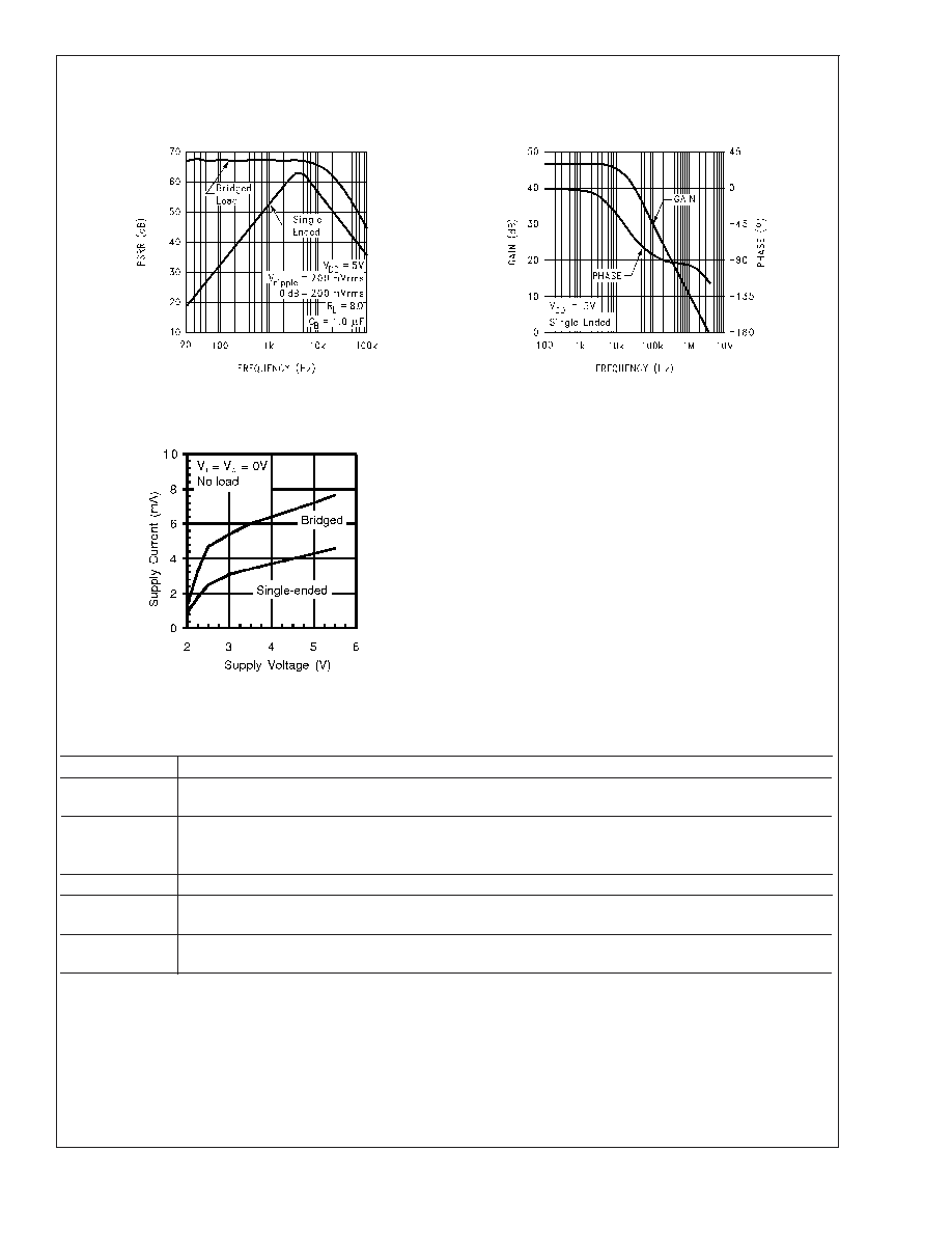
Typical Performance Characteristics (Continued)
Power Supply
Rejection Ratio
Open Loop
Frequency Response
20001321
20001322
Supply Current vs
Supply Voltage
20001323
External Components Description
Components
Functional Description
1.
R
i
Inverting input resistance which sets the closed-loop gain in conjunction with R
f. This resistor also forms a
high pass filter with C
i at fc = 1/(2
πR
iCi).
2.
C
i
Input coupling capacitor which blocks the DC voltage at the amplifier’s input terminals. Also creates a
highpass filter with R
i at fc = 1/(2
πR
iCi). Refer to the section, Proper Selection of External Components,
for an explanation of how to determine the value of C
i.
3.
R
f
Feedback resistance which sets the closed-loop gain in conjunction with R
i.
4.
C
s
Supply bypass capacitor which provides power supply filtering. Refer to the Power Supply Bypassing
section for information concerning proper placement and selection of the supply bypass capacitor.
5.
C
B
Bypass pin capacitor which provides half-supply filtering. Refer to the section, Proper Selection of
External Components, for information concerning proper placement and selection of C
B.
Application Information
ELIMINATING OUTPUT COUPLING CAPACITORS
Typical single-supply audio amplifiers that can switch be-
tween driving bridge-tied-load (BTL) speakers and single-
ended (SE) headphones use a coupling capacitor on each
SE output. This capacitor blocks the half-supply voltage to
which the output amplifiers are typically biased and couples
the audio signal to the headphones. The signal return to
circuit ground is through the headphone jack’s sleeve.
The LM4867 eliminates these coupling capacitors. Amp2A is
internally configured to apply V
DD/2 to a stereo headphone
jack’s sleeve. This voltage matches the quiescent voltage
present on the Amp1A and Amp1B outputs that drive the
headphones. The headphones operate in a manner very
similar to a bridge-tied-load (BTL). The same DC voltage is
LM4867
www.national.com
11
发布紧急采购,3分钟左右您将得到回复。
相关PDF资料
LM4867LQX/NOPB
3 W, 2 CHANNEL, AUDIO AMPLIFIER, PQCC24
LM4882MM/NOPB
0.48 W, 1 CHANNEL, AUDIO AMPLIFIER, PDSO8
LM4882M/NOPB
0.48 W, 1 CHANNEL, AUDIO AMPLIFIER, PDSO8
LM556ICN
DUAL PULSE; RECTANGULAR, TIMER, PDIP14
LM5756
3.5 A SWITCHING REGULATOR, 100 kHz SWITCHING FREQ-MAX, ZFM5
LM7001JM
PLL FREQUENCY SYNTHESIZER, 130 MHz, PDSO20
LM7001M
PLL FREQUENCY SYNTHESIZER, 130 MHz, PDSO20
LM7006
PLL FREQUENCY SYNTHESIZER, 400 MHz, PDIP20
相关代理商/技术参数
LM4867MT
制造商:NSC 制造商全称:National Semiconductor 功能描述:Output-Transient-Free Dual 2.1W Audio Amplifier Plus No Coupling Capacitor Stereo Headphone Function
LM4867MT NOPB
制造商:Texas Instruments 功能描述:Audio Amp Headphone/Speaker 2-CH Stereo 1.5W Class-AB 20-Pin TSSOP Rail
LM4867MT/NOPB
功能描述:IC AMP AUDIO PWR 3W AB 20TSSOP RoHS:是 类别:集成电路 (IC) >> 线性 - 音頻放大器 系列:Boomer® 产品培训模块:Lead (SnPb) Finish for COTS
Obsolescence Mitigation Program 标准包装:2,500 系列:DirectDrive® 类型:H 类 输出类型:耳机,2-通道(立体声) 在某负载时最大输出功率 x 通道数量:35mW x 2 @ 16 欧姆 电源电压:1.62 V ~ 1.98 V 特点:I²C,麦克风,静音,短路保护,音量控制 安装类型:表面贴装 供应商设备封装:25-WLP(2.09x2.09) 封装/外壳:25-WFBGA,WLCSP 包装:带卷 (TR)
LM4867MTE
制造商:Texas Instruments 功能描述:Audio Amp Headphone/Speaker 2-CH Stereo 3W Class-AB 20-Pin TSSOP EP Rail
LM4867MTE/NOPB
功能描述:IC AMP AUDIO PWR 3W AB 20TSSOP RoHS:是 类别:集成电路 (IC) >> 线性 - 音頻放大器 系列:Boomer® 产品培训模块:Lead (SnPb) Finish for COTS
Obsolescence Mitigation Program 标准包装:2,500 系列:DirectDrive® 类型:H 类 输出类型:耳机,2-通道(立体声) 在某负载时最大输出功率 x 通道数量:35mW x 2 @ 16 欧姆 电源电压:1.62 V ~ 1.98 V 特点:I²C,麦克风,静音,短路保护,音量控制 安装类型:表面贴装 供应商设备封装:25-WLP(2.09x2.09) 封装/外壳:25-WFBGA,WLCSP 包装:带卷 (TR)
LM4867MTEX
制造商:National Semiconductor Corporation 功能描述:Audio Amplifier Circuit, Dual, 20 Pin, Plastic, TSSOP
LM4867MTEX/NOPB
功能描述:IC AMP AUDIO PWR 3W AB 20TSSOP RoHS:是 类别:集成电路 (IC) >> 线性 - 音頻放大器 系列:Boomer® 产品培训模块:Lead (SnPb) Finish for COTS
Obsolescence Mitigation Program 标准包装:2,500 系列:DirectDrive® 类型:H 类 输出类型:耳机,2-通道(立体声) 在某负载时最大输出功率 x 通道数量:35mW x 2 @ 16 欧姆 电源电压:1.62 V ~ 1.98 V 特点:I²C,麦克风,静音,短路保护,音量控制 安装类型:表面贴装 供应商设备封装:25-WLP(2.09x2.09) 封装/外壳:25-WFBGA,WLCSP 包装:带卷 (TR)
LM4867MTX/NOPB
功能描述:IC AMP AUDIO PWR 3W AB 20TSSOP RoHS:是 类别:集成电路 (IC) >> 线性 - 音頻放大器 系列:Boomer® 产品培训模块:Lead (SnPb) Finish for COTS
Obsolescence Mitigation Program 标准包装:2,500 系列:DirectDrive® 类型:H 类 输出类型:耳机,2-通道(立体声) 在某负载时最大输出功率 x 通道数量:35mW x 2 @ 16 欧姆 电源电压:1.62 V ~ 1.98 V 特点:I²C,麦克风,静音,短路保护,音量控制 安装类型:表面贴装 供应商设备封装:25-WLP(2.09x2.09) 封装/外壳:25-WFBGA,WLCSP 包装:带卷 (TR)